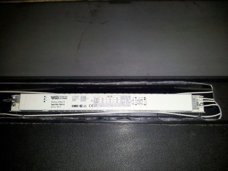
Hello again,
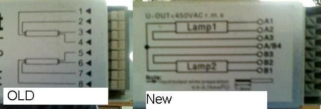
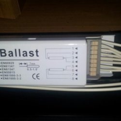
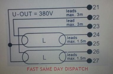
Is your schematic the same as in post No.187 in this thread? If so, then you definately have a cold cathode ballast.
Now, you only need to state your tube specs (e.g. 2 x 35W T8).
There is one small possible "gotcha" that you need to check on.. but first, this:
A cold cathode ballast nominally has 2 wires per tube (1 wire per tube end). Yes, you are correct that the tubes have 2 pins per tube end. Thes pins are connected (internally) to a heater/filament at each end of the tube. These heaters are electrically isolated from each other when the tube is off.
The cold cathode ballast does not use the heaters (initally) in the same way that a hot cathode ballast does (i.e. it does not need to preheat the heaters to start electron emission). A high voltage pulse is applied across the tube (end to end) which forces electron emission to begin. Once electron flow begins, the heaters glow due to electron flow in the tube. As the gases ionise, the resistance of the tube decreases, so allowing a greater current to flow. It is the primary job of the ballast to limit this flow to a safe level. Too high a current flow will destroy the tube.
This electron flow is high frequency AC, so the direction changes rapidly. The electron flow causes mercury and gas atoms to ionise inside the tube... The ions release their energy as UV light. It is the job of the phospor coating inside the glass tube to convert the UV to visible light. The exact chemical makeup of the coating defines the colour spectrum of light emitted.
Your specific ballast is designed to use either 1 or 2 tubes. If two tubes are in use, then one end of both tubes is connected together, with this connection also being terminated on the ballast.
You either need a ballast that supports this directly or you'll have to locate the wiring join, cut it and extend the 2 wires to the ballast.
Now, don't cut anything yet!! Just have a look at the wiring and see what you can see... If you could report back here then we'll know exactly what your options are.
Bodge99.

 /www.youtube.com/watch?v=XQvxXMlhOeo
