Led Build

StandbySetting

Fish Aficionado
Joined
Apr 1, 2011
Messages
4,383
Reaction score
203
Location
Void
Documentation so far:
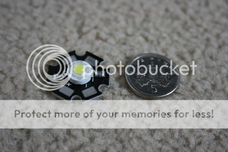
To give you an idea of the LED's this is how big they are in comparison with a 5P coin:
IMG_0458.jpg

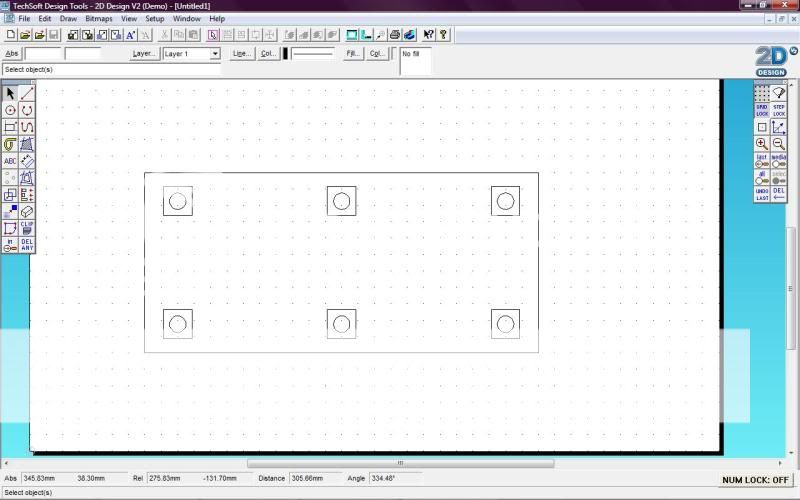
This is a basic diagram of the housing, with the circular pieces being the LED's and their mountings, the rectangles the heat sinks and the larger rectangle the foot print of the unit:
screen.jpg

The unit will measure 480*240*80mm.
IMG_0490.jpg

More progress:
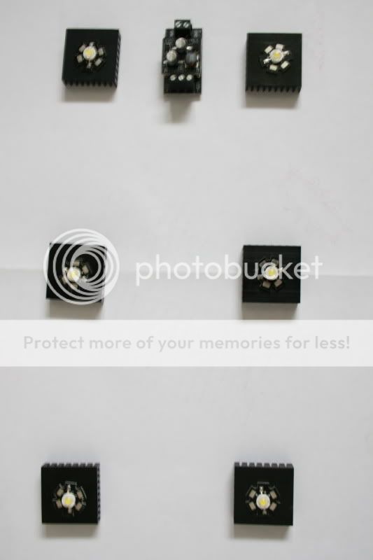
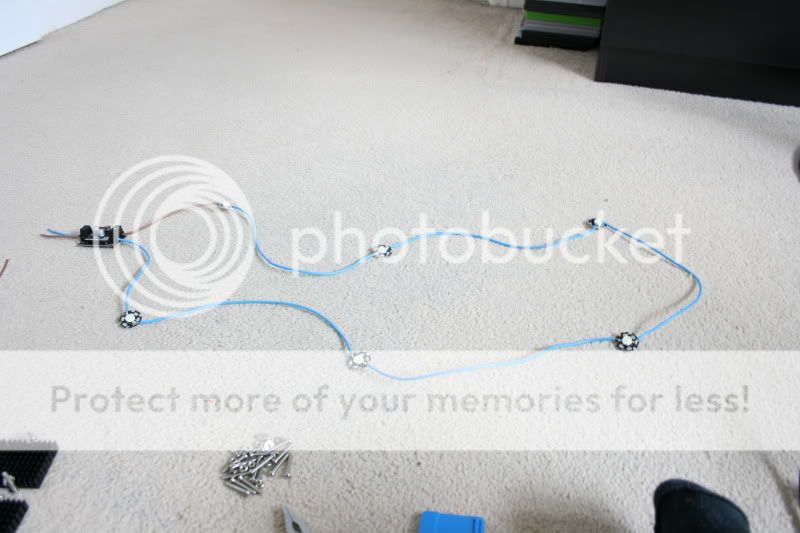
LED's and driver all soldered up:
IMG_0516-2.jpg

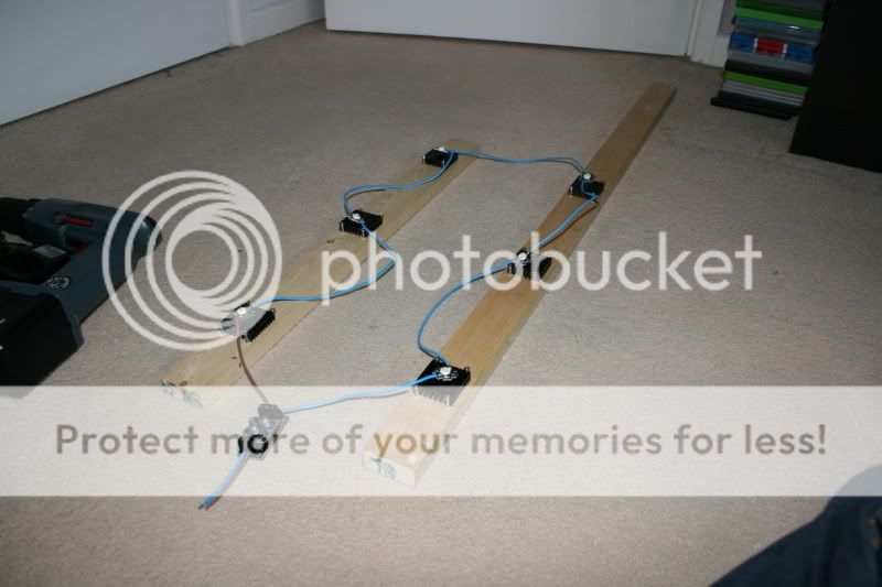
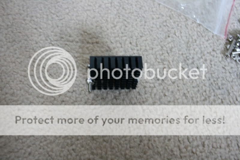
I've thought about how I was going to mount them, and this seems to be the easiest way:
IMG_0512-1.jpg

IMG_0513.jpg

The unit is beginning to come together:
IMG_0532.jpg

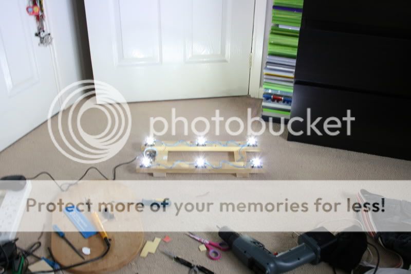
Wiring done for the turn on, had to a bit of fault finding after I had a faulty LED:
IMG_0575.jpg

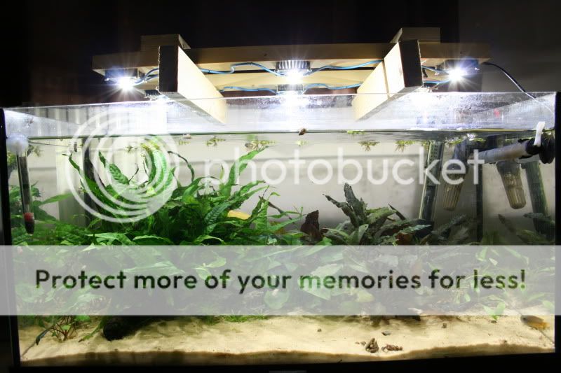
The result:
IMG_0577.jpg
 
I'll be following this article with a keen eye.
As I'm wanting a similar form of un-obtrusive lighting over a breeding set up
Thanks for your input
Regards
C
 
Most of the parts are here, heatsinks and driver arrived this morning, I just need to pick up some 1A wire, heat paste or pads and the transformer, oh and some m3/4 long bolts to secure everything into place, I'm using some corrugated PVCu off cuts to help mount each LED and its respective heatsink.

One thing that worries me is though, the driver puts out 688mA I'm just hoping it will be enough to power the 700mA LED's, I'm not really sure how current affects a circuit (I hated electronics theory), if anyone knows I would be grateful to hear! I presume they either wont light or they'll just run slightly dimmer?

Here's a very crude pick (loads of camera shake) as it was taken from above and my hands aren't steady!
IMG_0490.jpg

By the way, the LED's I am using have a colour temperature of 6000 Kelvin, good colour for freshwater.
 
Based off of my work with laser diodes (~3.5 total years) you should be fine. The spec sheet for our laser diode quotes the operation current is a minimum of 90 mA but this is simply not the case (caveat: they may intend this to mean the minimum current to achieve "lasing", however this is still incorrect as I can have it lase around 29 mA). The only thing I notice that changes with current is wavelength of the light output (but this is such a small change that is noticed in my work that will not be noticed in your broadband application) and the intensity of the light output. Thus, I would imagine the worst case scenario is your LED will run a little lower output than you expect. This can be good as some claim that the LED will last longer due to the slower degradation of the phosphor coating in the diode. Hope this helps!
 
I haven't yet, they were just placed on for the photo, but I will be using thermal pads or paste, whichever is cheaper, thermal paste is generally the better option though as it conducts heat better.
 
I haven't yet, they were just placed on for the photo, but I will be using thermal pads or paste, whichever is cheaper, thermal paste is generally the better option though as it conducts heat better.

Paste isnt like glue though, its fine for a CPU clamped in place on a motherboard, but it wont "fix" it to the heatsink which is what i think the OP was asking. Im following LED threads with interest too! :D I suppose you could superglue the outer edges down but since paste has a tendancy to burn off after a fair few months and it might need applying again.
 
That was the plan, just to use the thermal grease and then superglue the outside, I doubt these would get hot enough to burn away the glue though, but I'll have to see, I'll probably get self adhesive thermal pads instead as they're easier to apply.
 
Not sure what is available to you in the UK, but double-sided thermal conducting tape works wonders for securing equipment. Again, use this stuff in the lab and you have to about break the device to get it off the table (tape is between device and table). Here is a link, very expensive but gets the idea across.
 
Nice one,
I haven't seen that tape before!
I bet you can get it from rapid in the UK.
 
Cheers for that, I'll see if I can get some from Maplin tomorrow, probably quite expensive but I want to crack on with it.
 
A bit of progress:

LED's and driver all soldered up, just waiting for the arrival of the PSU:
IMG_0516-2.jpg

I've thought about how I was going to mount them, and this seems to be the easiest way:
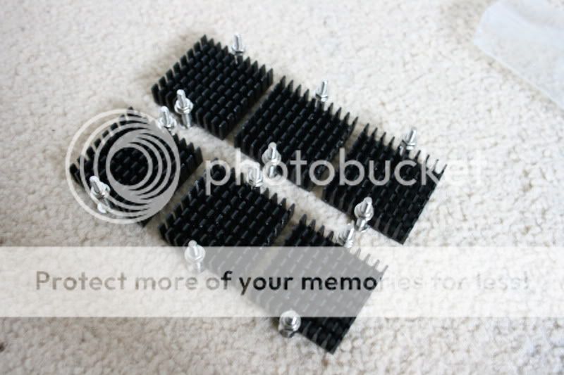
IMG_0512-1.jpg

IMG_0513.jpg


There will be about a 3-5mm gap between the heatsink and the wood it'll be mounted to, thermal tape ordered too.
 

Most reactions

Back
Top