Underwurldes - Diy Auto Top Off Project

:yahoo: Parts arrived today :yahoo:

One problem... Failed to notice that the 1K resistors were on backorder :blink: I didn't even think to look. I mean come on, they're 1K resistors, who runs out of those :unsure: :rolleyes:. Thats no big deal though, I can raid the electronics shop's stuff so long as I re-stock when my backorderd stuff comes in :D :D

Construction will commence on Sunday afternoon/evening.
 
Hey Andy, I've started assembly over here and lacking your wonderful PCB have some wiring questions for you. The biggest one that I have is for the wiring of IC4. In your diagram, you show pin 2 of IC4 going to pin 1 of Con4 with an X in the middle of the wire. You also show a dashed line from pin 2 of IC4 to pin 4 of IC2B. Are you trying to show some sort of option here? Just curious as the drawing is confusing.

One other simple question. SW2, the enable/disable switch needs to be a latching switch, not a momentary switch correct? Looks like I ordered a momentary switch, whoops :blush:. No matter, got tons of latching ones layin around :D
 
Sorry, sorry, sorry Ski!

It's 'that time of year' and also the whole family here have been down with a rather nasty cold bug which has knocked me out for for the last 2 weeks!

OK, your questions:
When designing this I had no idea of the polarity of the float switches used: I did not know if they were normall open (N.O.) or normally closed (N.C.), hence I used a spare gate on IC2 as an inverter for the float switch input signal...

So, 'normal' operation (as found to be correct wiring by sophos9) is:
Connect Con4 pin1 to pin 2 of IC4. Ignore IC2b, you don't need to wire it in at all: You can still wire it in if you want by connecting Con4 pin1 to pins 5&6 of IC2B at the same time, just that the output of IC2B pin 4 goes nowhere (leave it open circuit and don't connect it to anything).

IF you do find that you need to invert the logic of the float switch, disconnect the wire from Con4 pin 1 to IC4 pin 2 and instead connect from IC2B pin 4 to IC4 pin 2.

Clear as mud? :blink:

Indeed the switch need to be latching & not momentary.

Hope that helps...

Andy
 
Heh, don't worry about it Andy, I messed up my back and haven't really been able to sit at a desk to do some soldering anyways. Too much pain :S
 
I feel your pain dude....

7 years ago I was diagnosed with A.S. (Ankylosing Spondilitis).

Christ-on-a-bike the pain I have been in has been unbearable ... in escapable.

I'm OK now... but I still can't run (both my ankles are the size of tennis balls).

Anyway, less of my whinging, HAPPY NEW YEAR!!!!!

Andy
 
Not so great on this project, kinda stalled for the time being :). Got a PM question for you though...
 
Andy, now I have to admit - that is pretty amazing mate!!!

Would you be able to export to a larger size, I'm looking over it to get the parts ordered but cannot see what some of them are and I'll then get it dropped into a stripboard layout

I think you have just built the most comprehensive DIY circuit on the web for auto top offs!!! :hey:

Thanks loads


Hi all,

I was searching for a schematic for a simple way to have 
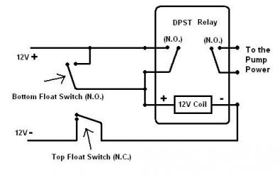
adjustable hysteresis without any circuitry (using a 555 etc) for my brother to use (who doesn't fair well with a soldering iron) and needed to keep his pump from cycling on and off so often. I didn't find any, -_- but came across this forum. :fish:

I drew this schematic up and think you may find it useful...

pumphysteresisrelayintegj2.jpg


(the hysteresis is all up to how far you place your float switches apart)

You can use any voltage relay (buy a relay at whatever voltage wall adatper you have handy - old cell phone chargers work great, anything that has a steady voltage) (Anything over 24V is to be avoided in water (death is not fun)) :oh:

The relay can be DPST or DPDT as you only need the two N.O. contacts.

Normally Closed = (N.C.)
Normally Open = (N.O.)

Shopping at digikey.com or ...

Digi-Key.com (with "In Stock" button checked, and in the "Power Relay" category)

- you can shop buy...
1) the coil voltage (to match your wall adaptor) hit the "In Stock" button and "Apply Filters"
2) hold 'Ctrl' and select both DPST & DPDT, hit "Apply Filters"
3) pick "Non Latching, Standard" and hit "Apply Filters"

Now you can select the lowest 'Coil Current' relay as this will give you the longest life on your float switches. These have reed switches in them that are usually rated to switch 50mA or less for millions of cycles (depending on the switch). Switching more current makes them not last as long and they could eventually weld together.

Hope someone enjoys this! :yahoo:
 

Attachments

  • Pump_Hysteresis_Relay_Interlock_Schematic.JPG
    Pump_Hysteresis_Relay_Interlock_Schematic.JPG
    17.5 KB · Views: 71

Most reactions

Back
Top